AN OVERVIEW OF GEORADAR EQUIPMENT

A Georadar Equipment is a machine used to detect underground components and layer densities. It uses waves to obtain data on various structures beneath the ground and showcases those details on a monitor for people to see what is contained underground. Depending on the area under investigation, people can adjust how far in the ground they would like the geo-radar equipment to investigate. You can control the machine to give you finer and specific details of the place in which you are investigating so that you know exactly what to do on your earthwork projects.

Accessories Needed in Georadar Equipment Working

The Georadar Equipment can work on its own for minor investigations but for those who want to see deep, you will need an antenna. There is an antenna for cars and trailers so depending on the type of vehicle you have, use the appropriate type of antenna. You can decide to use the RADAN software version of your choice but the machine normally comes with its own software.

Used in Roads and Pavement Analysis

Georadar Equipment has many areas of application and chief among them is road and pavement analysis. It is able to detect road layer density and determine whether the road or pavement is able to withstand the pressure applied on it or not. Results are used to determine the kind of road improvements that should be done to make the roads and pavements top quality and robust. In other areas, Georadar Equipment is used in detection of minerals so that miners know the exact distance to drill before they reach for those minerals. It is simple and easy to determine the components of the ground so that people can know the precise intervention to take when doing earthwork projects.

Besides its accuracy and reliable in communicating findings, Georadar Equipment allows for non-destructive ground investigation. No laborious efforts are needed to know what is in the ground so it spares time and minimize resource wastage. There are many types and variations of Georadar Equipment so you can choose what is essential for your projects.
WORKING OF SOIL EXTENSOMETER AND ITS APPLICATIONS

Technology today has penetrated into all the industries to such an extent that there is no on-site problem that cannot be solved. Right from reconnaissance to final touches, every activity across all industries rely on various equipment to guide them to do a good job. Especially in the construction industry where the stakes are high, using precision equipment to ensure safety of the structure is a highly important job. It is important also to determine safety of the soil on which construction is to be done – things like settlement and movement can collapse a building easily. To understand mobility characteristics of soil, extensometers are used. In this blogpost, you will get to know about working of extensometer and its applications.

How does extensometer work?

Most extensometers work on the principle of measuring displacement directly with the help of flanges and a telescopic rod. Extensometers consist of two flanges connected with a telescopic rod, which contains a measuring scale. These flanges are meant to be inserted into the soil in which displacement is to be measured. As soil moves more and more, the distance between both the flanges increases, which causes the telescopic rod to start showing measurement of the displacement in standard units.

Applications of extensometers

These instruments find applications across many activities in the construction industry, for example:

  • Settlement monitoring in excavations, embankments and foundations
  • Monitoring embankment spread
  • Monitoring underground conduit convergence
  • Monitoring rock slide, wall and abutment movement
  • Monitoring soil consolidation
  • Monitoring tunnel and mine subsidence

Soil extensometers are wonder devices that allow monitoring safety of a lot of operations during construction.

A Brief Guide on the Importance of Concrete Geometry Testing

Non-destructive testing is typically favoured over conventional destructive tests as it helps save money and time, especially when examining materials like concrete. Concrete geometry testing involves a range of equipment that can determine rebar location and cover foundation depths and slab thickness. The following is an overview of concrete geometry testing equipment and their importance for the job:

  • Foundation test gauge – The device is a compact shaft and pile inspection tool that uses sonic echo testing method, which is also known as ‘pile integrity test’ (PTI). Sonic echo investigations are conducted to determine the length and integrity of deep foundations. They may be conducted on a shallow wall structure, too, and on different materials such as steel, concrete, and wooden piles. The various applications of a foundation test gauge include week and uncured concrete in cast piles, determining the foundation depth, and assessment of the condition of foundations. It may be used to investigate bulbs and damage to foundations, as well as the inclusion of water or soil in cast piles.
  • Borehole probe cover meter – This meter detects reinforcing bars near a hole drilled in the concrete. The system consists of a handheld battery-power device with a diameter probe that measures 10mm. It can be used for measuring clearance from reinforcing bars for a hole where anodes for cathodic protection are placed after drilling. However, it may not be efficient in measuring the depth of the reinforcing steel or determining where the reinforcing bars are.
  • Devices for ultra-seismic investigations – Ultra-seismic investigations, as a form of concrete geometry testing, can determine and evaluate the length and integrity of deep and shallow piles or foundation elements. Hence, it is suitable for many different structures, including deep-drilled piles, shallow wall-shaped substructures, and when it is impossible to access the foundation element’s top surface. Structures can be analysed properly as long as the structure is exposed from one to 1.8m where the instrument can be mounted. Using ultra-seismic devices, you can conduct structural investigations, assess the foundation’s condition for geotechnical assessment, and investigate damage and bulbs in foundations.

Top 10 Unusual Finds by Ground Penetrating Radar (GPR)

The ground penetrating radar is among the most advanced geophysical methods that uses high-frequency radio wave pulses for subsurface imaging. It is used in many applications, including civil engineering, archaeology, and engineering. As it scans the subsurface, GPR is likely to find a wide variety of objects, including unusual ones that have surprised a lot of people. Here are some of them:


  1. Mass graves – The ITCCS used ground penetrating radar in Brantford, Canada, leading to a gruesome discovery around 15 to 20 feet underground. Bodies of several children who attended to Mohawk Institute were found. The school itself is notorious for its dark past.
  2. Ahuizotl’s long lost tomb – Archaeologists used GPR to see what is under a colonial Spanish building, which was destroyed in a 1985 earthquake. They found a lot of underground chambers and the remains of an Aztec emperor who ruled during the time of Columbus.
  3. Petra’s Shrine and lower market – In 2001, GPR was used to test Petra’s underground, revealing different structures like a shrine, an ancient garden within a pavilion, and a lower market.
  4. A mammoth – A farmer found a huge bone in a field in Iowa, USA. He kept finding more bones over the years and kept them in his home all this time. Eventually, he called the University of Iowa to identify the animal where they came from. The GPR team recovered over 30 bones from the farm.
  5. A forgotten Roman settlement – A previously unknown settlement was discovered in Vescovio due to ground penetrating radar. The findings included the villa of Marcus Ulpius Traianos, a Roman emperor. The villas are notable for having two dipping pools in its bathhouse. GPR helped locate a marketplace, a second century AD amphitheatre, and a series of Roman crypts, too.
  6. Noah’s Ark – Military satellite imagery and ground penetrating radar were used to find a structure, which scientists are claiming to be Noah’s Ark, on Mt. Ararat, Turkey. Two large pieces were reportedly found in glacial ice.
  7. The remains of Pumapunku, Bolivia – Incans believed Pumapunku to be the site where everything began. The temple is an ancient wonder that was discovered via GPR and its digital imaging technology.
  8. Live 1000lb bombs from World War II – GPR located three live American bombs dating back to Second World War in Germany. They were found in an old BMW fabrication plant and were successfully defused before they were removed.
  9. Bodies and artefacts from 1832 – Official stories stated that Irish immigrants have died of Cholera, but a family believed that their grandpa, who was among the ones who perished, was killed and dumped in a mass grave. GPR helped uncover thousands of artefacts and seven bodies who were found to have been murdered.

Roman Gladiator School – A GPR with a multi-antenna system located a 2,800-square metre compound that was used to train Gladiators. Located in Vienna, Austria, the settlement has multiple buildings around a central training area, which had wooden spectator stands. There is a cemetery for gladiators, too.

Know about the Typical Working Method of Direct Shear Test Apparatus

A direct shear test is one which is conducted in the field or in the laboratory to determine the capacity of materials- usually soil or rock, to resist shear.

The property of shear strength of soil or rock type is one of the major properties that are to be taken into consideration by engineers when considering the construction of structures that are dependent on the shearing resistance of the given soil or rock type. Some such conditions are calculating slope stability or determining the capacity to support foundations.

An Apparatus for conducting a Direct Shear Test consists of multiple components, one of which is a box that comes in a square like or circular shape and is segmented into two compartments. It is basically a box which splits horizontally. The sample that you want tested is to be put in this box. Thereafter, two kinds of forces are applied on the box to determine the shear strength of the material. There is a constant downward load that the sample or specimen is subjected to, while an increasing degree of horizontal force i.e. a force parallel to the surface of the specimen is applied on one of the two halves of the box. This leads to the two parts of the shear box to be “pulled apart”. These two forces create a shear failure that runs along the meeting points of the two halves of the box. The apparatus records the value of normal load as well as the shear force. Controlling the speed at which horizontal force is applied, determines the degree of strain.

A loading unit is another component of the apparatus. It is usually provided with roller strips or V strips to ensure that the shear box which rests on it has frictionless movement. The loading unit is also provided with load yokes to ensure balance to it. There is also a lead screw which connects to the shear box structure and helps applying shear stress.

In order to arrive at a decisive conclusion about the shear strength of a specimen, the test is usually carried out thrice, each time with different degrees of vertical load. This allows engineers to graphically chart out a distinctive “failure envelope” and consequently make well informed plans and designs for slopes, dams or foundations.

Though a shear test can be performed to measure the shear strength of different surfaces, they are mostly conducted to measure the amount of shear strength that sandy materials have.

APPLICATIONS OF GROUND‐PENETRATING‐RADAR ON CONCRETE SURFACE

The ground penetrating radar system is quite a useful tool with its ability to locate underground utilities with relative ease. It ensures the safety of existing construction beneath the ground while excavation is in progress for new constructions. Ground penetrating radar can also be used on concrete surfaces. Here is a blogpost telling you about applications of ground penetrating radar on concrete surface.

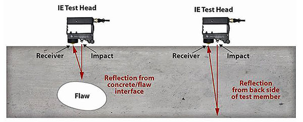
The most impressive use of GPR in concrete is to locate the reinforcement bars inside. There are times when drilling or other invasive operation is to be carried out in a concrete structure. To ensure that sufficient cover is left for the rebars, GPR is used to map the mesh inside the concrete form.

The ability of GPR to distinguish between layers of different materials helps to map interfaces between concrete and other surfaces. This comes in handy while determining pavement thickness, as the radar detects soil-concrete interface. So many important applications of GPR are found with concrete itself. Try using it today.


Procedure of Using Laboratory Crushing Equipment

Laboratory crushers are used for crushing core samples, aggregates, and similar objects when their size needs to be reduced. There are different types of laboratory crushing equipment, and they typically consist of a jaw and a control panel. Their construction is usually robust, with a housing or a case that conforms to CE requirements. Here are some types of laboratory crushing equipment and how to use them.

  • Jaw crusher for milling and crushing – A 380 V, 50Hz laboratory type jaw crusher is designed for crushing materials when smaller particles are required for testing. It can be supplied in different sizes, depending on your capacity, output grain sizes, and the feed requirements.
  • Adjusting the grain size – Accessories, like the Hammer mill, can further reduce the size of the grain the machine can produce. A basic lab crusher should have a maximum feed size of 100x100mm, and it should produce grain that is up to 8mm in size. The crushing mechanism is adjustable to produce grain at the right size. Other types of laboratory crushing equipment have a maximum feed size of 10mm or 20mm, and they produce grain size that is up to 10μm or 0.5 to 2.0mm in size, with suitable sieves. Make sure the device conforms to ASTM C289.
  • Adjust the jaw – The jaw’s movement is adjustable from 5mm to 15mm, which should be enough to accommodate the size of your samples.
  • Observe safety precautions – As with any lab equipment, operators are required to wear protective gear or clothing when operating laboratory crushing equipment. That way, they can minimise their risk of getting into an accident, such as when debris flies out from the machine. It is important to switch off and unplug the machine when not in use and to not leave it unattended, as to prevent unauthorised use.

Soil Compaction Testing Equipment and Its Application

Soil compaction testing is one of the most crucial tests in geotechnical engineering, and it is done using special types of equipment designed for in-situ or laboratory testing. Soil testing lets construction companies and engineers obtain the information they will need to predict the soil’s mechanical behaviour. That way, they have a reliable and accurate basis when building and designing foundations and support for other infrastructure, like roads. Soil compaction testing equipment must be able to characterise soil samples and support sample collection, mechanical property evaluation, soil classification, and the testing of completed sub bases and road bases on site.

Soil Compaction Testing Equipment

Some of the most commonly used soil compaction testing equipment help determine the California Bearing Ratio (CBR), plastic and liquid limit, shrinkage, and Atterberg limits. All types of equipment for soil compaction testing in Australia must comply with Australian standards. The use of a specific type of equipment and the testing process are conducted following certain standards, too. For example, CBR testing procedures are described in AS 1289.6 for lab-prepared samples.

California bearing ratio test machines measure the load-bearing capacity of the soil used for roads. They are used to identify the load bearing capacity of soils under a paved airstrip or unimproved airstrip. When conducting a CBR test, higher numbers depict a harder surface. For instance, a tilled farmland can have a CBR of 3, and moist clay can have a CBR of 4.75.

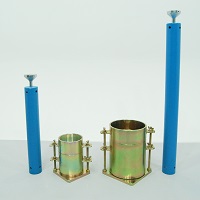
Compaction hammers and proctor or compaction moulds are essential tools for soil compaction testing equipment. Rammers and moulds are utilised to determine the link between the moisture content and density of compacted soil. Ideally, the mould is constructed of plated steel, with a base plate, mould body, and collar. Rammers are built from plated steel and utilised for compacting soil samples in a compaction mould. Proctor penetrometers determine fine grained soil’s moisture-penetration resistance.

Measure Dry Film Thickness with a Coating Thickness Gauge

Dry film thickness is among the most important measurements because it provides information on a substrate’s expected lifespan, appearance, and suitability for an application. Likewise, it helps ensure the coating’s compliance with international standards. Coating thickness over concrete can be determined easily in a non-destructive manner with an ultrasonic device. A concrete thickness gauge can help you determine dry film thickness insitu. Likewise, it is useful in determining the coating thickness on other materials, like plastic and wood.

ctg2-principle

A high-end coating thickness gauge comes with a probe that emits high-frequency sound pulses, which go through the coating via coupling gel. The pulse can reflect from any surface that has a different density from it. Dry film thickness is determined by measuring the time it takes for the ultrasonic signal to travel from the probe to the substrate or coating interface, and back. For this reason, it is crucial to pick the right probe that will suit the material you are testing. The probe you choose determine the precision of the measurement and the maximum thickness that can be measured, it is best to select a unit that measures slightly more than the maximum expected thickness of your coating.

Take a note of the substrate when choosing your probe. Reputable manufacturers and providers of industrial testing equipment can provide different types of probes for measuring dry film thickness made using polymer on plastic and wood, soft and thick coatings on asphaltic neoprene, extremely thick polymers, and polyuria, and coatings on fibreglass and concrete. There are also separate systems suitable for use over ferrous or nonferrous metals. Standard coating thickness gauges can measure the overall thickness of the coating system, while advanced ultrasonic models can measure a coating system’s total thickness or up to three individual layers of thicknesses in multi-layer systems.

A coating thickness gauge will ensure accurate and quick readings on dry film thickness measurements. High-end devices come with a graphic readout, which can be helpful when you need to analyse the coating system in detail. Consider a coating thickness gauge that is rugged, equipped with a colour LCD, and capable of resisting dust, water, oil, acid, solvent, and shocks.

Things One Should Know About a Universal Testing Machine

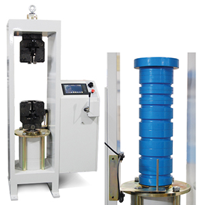
The universal testing machine is a must have equipment if you constantly need to measure force and the deformation it can cause on various materials. One of the most common applications of universal testing machines is testing the performance of steel reinforcing bars when they are placed under significant tension. Certain factors must be considered when choosing universal testing equipment, and here are some of them:

universal-tension-compression

  • It should be able to conduct different tests and measurements – Universal testing machines can be tailored to conform to various standards and conduct certain types of tests with the addition of some accessories, like fixtures, load cells, platens, and grips. Equipment providers can provide customised solutions, which most physical testing laboratories require. A basic equipment should be able to conduct tensile, flexural, shear, and compression tests.
  • How data is acquired – The applied force and the resulting deformation are measured via electrical signals sent to a recording device or a computer, which runs a software for data acquisition and analysis. Older analogue universal testing machines had a chart recorder, and modern, cutting-edge equipment use computers or data loggers, software, and digital controls. The usual load and deformation curves represent the force on Y-axis versus deformation on X-axis.
  • The AS, ISO or ASTM standard for a particular test – Every material must be tested following national recommendations and globally accepted standards. Hence, be sure to determine the type of test the universal testing machine will do. Flexural testing, for instance, is conducted according to ISO 178 and ASTM D790, and compression tests conducted on rigid cellular plastic foams are accomplished following ISO 844 and ASTM D1621. Some tests, particularly those that are conducted for medical, aerospace, and automotive devices, may require testing following OEM standards.
  • Configuration – A universal testing machine typically consists of a single or double vertical load bearing columns where a fixed base horizontal plate is mounted along with a moveable horizontal crosshead above. Modern machines have columns made from a ball screw drive to enable the positioning of the moveable crosshead. This way, the workspace is maintained between the moving crosshead and the base of the machine.