Types of GPR and Their Uses

GPR stands for ‘ground penetrating radar’ and it is a non-destructive geophysical method for detecting objects from the subsurface. Ground penetrating radar uses radar pulses and electromagnetic radiation in the radio spectrum’s microwave band for imaging, as it detects reflected signals from subsurface structures. Hence, it is widely used in a range of applications and on various surfaces, like pavements, fresh water, ice, rock, structures, and soil. As long as, the conditions are right, operators can rely on GPR to find subsurface objects, cracks, voids, and changes in the properties of materials underground.

The most basic type of GPR offers fast and reliable on-site imaging for drilling, coring, and cutting, and the characterisation of concrete slabs with missing or limited design drawings. It uses radio waves to find objects, which have different dielectric constants. Hence, materials like metals, filling, and plastics can easily be found within concrete. It can scan depths of up to 0.5m, where cover metres are typically limited to a range of 150mm to 200mm, making it ideal for rebar, post tensioning, and locating services.

Another type of GPR is a utility locator with a touch-screen controller that can take depth slices quickly, and export site reports wirelessly exported with geo-located data. The software enables off-site analysis and review, as well as global positioning locations complete with site photographs, Google Maps, or CAD. The rugged equipment comes with an intuitive touchscreen and an ergonomic lightweight trolley. The GPR is used for marking and locating pipes, utility lines and services, and other buried objects, like tanks. It can be used for creating reports and maps based on the locations and images generated from scans. It is also useful in civil engineering applications, archaeology, and geology.

First-generation utility location GPR is cost-effective for taking pictures of an underground infrastructure. Hence, it is typically used in finding metallic or non-metallic utilities, undocumented utilities, utilities with broken tracer wires, disturbed soil due to utility burial, and buried structures or unexpected obstacles, like old foundations, which can cause issues during construction and excavations. The equipment comes with a cutting-edge ground penetrating radar sensor, a robust battery, built-in odometer, and an instant response display.
Procedure of Using Laboratory Crushing Equipment

Laboratory crushers are used for crushing core samples, aggregates, and similar objects when their size needs to be reduced. There are different types of laboratory crushing equipment, and they typically consist of a jaw and a control panel. Their construction is usually robust, with a housing or a case that conforms to CE requirements. Here are some types of laboratory crushing equipment and how to use them.

  • Jaw crusher for milling and crushing – A 380 V, 50Hz laboratory type jaw crusher is designed for crushing materials when smaller particles are required for testing. It can be supplied in different sizes, depending on your capacity, output grain sizes, and the feed requirements.
  • Adjusting the grain size – Accessories, like the Hammer mill, can further reduce the size of the grain the machine can produce. A basic lab crusher should have a maximum feed size of 100x100mm, and it should produce grain that is up to 8mm in size. The crushing mechanism is adjustable to produce grain at the right size. Other types of laboratory crushing equipment have a maximum feed size of 10mm or 20mm, and they produce grain size that is up to 10μm or 0.5 to 2.0mm in size, with suitable sieves. Make sure the device conforms to ASTM C289.
  • Adjust the jaw – The jaw’s movement is adjustable from 5mm to 15mm, which should be enough to accommodate the size of your samples.
  • Observe safety precautions – As with any lab equipment, operators are required to wear protective gear or clothing when operating laboratory crushing equipment. That way, they can minimise their risk of getting into an accident, such as when debris flies out from the machine. It is important to switch off and unplug the machine when not in use and to not leave it unattended, as to prevent unauthorised use.

Soil Compaction Testing Equipment and Its Application

Soil compaction testing is one of the most crucial tests in geotechnical engineering, and it is done using special types of equipment designed for in-situ or laboratory testing. Soil testing lets construction companies and engineers obtain the information they will need to predict the soil’s mechanical behaviour. That way, they have a reliable and accurate basis when building and designing foundations and support for other infrastructure, like roads. Soil compaction testing equipment must be able to characterise soil samples and support sample collection, mechanical property evaluation, soil classification, and the testing of completed sub bases and road bases on site.

Soil Compaction Testing Equipment

Some of the most commonly used soil compaction testing equipment help determine the California Bearing Ratio (CBR), plastic and liquid limit, shrinkage, and Atterberg limits. All types of equipment for soil compaction testing in Australia must comply with Australian standards. The use of a specific type of equipment and the testing process are conducted following certain standards, too. For example, CBR testing procedures are described in AS 1289.6 for lab-prepared samples.

California bearing ratio test machines measure the load-bearing capacity of the soil used for roads. They are used to identify the load bearing capacity of soils under a paved airstrip or unimproved airstrip. When conducting a CBR test, higher numbers depict a harder surface. For instance, a tilled farmland can have a CBR of 3, and moist clay can have a CBR of 4.75.

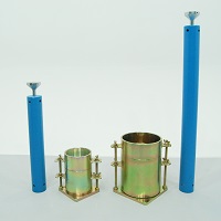
Compaction hammers and proctor or compaction moulds are essential tools for soil compaction testing equipment. Rammers and moulds are utilised to determine the link between the moisture content and density of compacted soil. Ideally, the mould is constructed of plated steel, with a base plate, mould body, and collar. Rammers are built from plated steel and utilised for compacting soil samples in a compaction mould. Proctor penetrometers determine fine grained soil’s moisture-penetration resistance.

Measure Dry Film Thickness with a Coating Thickness Gauge

Dry film thickness is among the most important measurements because it provides information on a substrate’s expected lifespan, appearance, and suitability for an application. Likewise, it helps ensure the coating’s compliance with international standards. Coating thickness over concrete can be determined easily in a non-destructive manner with an ultrasonic device. A concrete thickness gauge can help you determine dry film thickness insitu. Likewise, it is useful in determining the coating thickness on other materials, like plastic and wood.

ctg2-principle

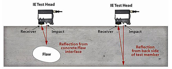
A high-end coating thickness gauge comes with a probe that emits high-frequency sound pulses, which go through the coating via coupling gel. The pulse can reflect from any surface that has a different density from it. Dry film thickness is determined by measuring the time it takes for the ultrasonic signal to travel from the probe to the substrate or coating interface, and back. For this reason, it is crucial to pick the right probe that will suit the material you are testing. The probe you choose determine the precision of the measurement and the maximum thickness that can be measured, it is best to select a unit that measures slightly more than the maximum expected thickness of your coating.

Take a note of the substrate when choosing your probe. Reputable manufacturers and providers of industrial testing equipment can provide different types of probes for measuring dry film thickness made using polymer on plastic and wood, soft and thick coatings on asphaltic neoprene, extremely thick polymers, and polyuria, and coatings on fibreglass and concrete. There are also separate systems suitable for use over ferrous or nonferrous metals. Standard coating thickness gauges can measure the overall thickness of the coating system, while advanced ultrasonic models can measure a coating system’s total thickness or up to three individual layers of thicknesses in multi-layer systems.

A coating thickness gauge will ensure accurate and quick readings on dry film thickness measurements. High-end devices come with a graphic readout, which can be helpful when you need to analyse the coating system in detail. Consider a coating thickness gauge that is rugged, equipped with a colour LCD, and capable of resisting dust, water, oil, acid, solvent, and shocks.